EDID Management

A Brief History of EDID Management
With the availability of a wide range of signal types, display devices and processing products, it becomes difficult for video system users to optimize the output timings of source devices for all of the different kinds of display devices to which they can connect. Fortunately, the Video Electronics Standards Association (VESA) recognized this potential problem long before the proliferation of digital display devices. In 1994, VESA introduced a standard by defining an interface through which data about the display device could be communicated to source devices.
This interface, the Data Display Channel (DDC), was first implemented as part of the DVI standard, and later retrofitted to the SVGA standard, designed to work with VGA cables with blue connector shells. The data transmitted on the DDC (and defined within the DDC standard) is known as Extended Display Identification Data (EDID). DDC and EDID have been incorporated into digital display standards such as DVI, HDMI®, and DisplayPort.
EDID Overview
When a source is first connected to a display, a “hot plug” event takes place to let the source know that a display or other “sink” device has been connected. In this, a source device generates a low voltage signal which is sent to, and returned by, a display device. Upon detection of the hot plug event, the source device issues a DDC “EDID Read” command to the destination device. In response, the display transmits its EDID file to the source device. This EDID file contains information about the display’s preferred (native) resolution, as well as information about other supported resolutions, color space, bit depth, and the audio formats it supports.
Additional types of information that can be conveyed through the DDC include:
- Manufacturer name, product serial number, and date of manufacture
- Product type
- Timings supported by the display
- Display size
- Color space conversion
- Pixel mapping data
For simple systems consisting of a single source and single display device, the transfer of EDID information is straight-forward and works quite well. But for larger systems with multiple sources, displays, switchers and signal processors of various types in the signal chain, EDID transmission can become problematic, since the sources may receive conflicting information from various “sink” devices (i.e. different video displays). In other cases, a source may not be able to accurately read EDID information causing a disruption in the display. Thus, effective EDID management has become a critical issue for commercial, professional and industrial AV installations.
Industry Problem: Routing a source between displays of different native resolutions can cause the source to switch resolutions every time it is routed, leading to disruption in the video output.
RGB Spectrum Solution: RGB Spectrum products offer Total EDID Manager, a solution that enables input cards to provide consistent EDIDs to source devices, regardless of where they are routed, for seamless image display.
EDID Management Sample Use Cases
To understand the benefits of an EDID management system, let's consider some typical use cases:
- The sources input to your display processor look best at a higher resolution than the native resolution of the displays connected to the processor’s outputs. With an EDID management system, you can choose a high native resolution EDID, which is suitable for your source devices, from the EDID list and use that as a fixed EDID at the input. In this way, you can display full resolution windows spread across multiple displays.
- Your processor is usually connected to a wall of displays with a fixed resolution, but you would like to test and develop material offline while connected to some smaller multi-sync monitors with a different native resolution. You can capture the EDID of one of your wall displays, and use this as the emulated EDID of the processor’s output. This will allow your tests and final presentation to have the same pixel dimensions as the original wall displays.
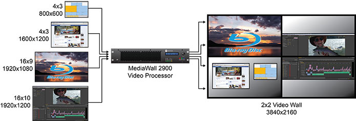
- You have a diverse set of inputs, each with different pixel dimensions and aspect ratios, which were originally displayed on monitors of different sizes and shapes. You would like to display each source as a window at its original pixel dimensions on a video wall or Ultra High Definition (UHD) display. To accomplish this, you can capture the EDID from each of the original monitors, and set these as fixed EDIDs at each of the inputs (see diagram below).

In this diagram, the original pixel dimensions and aspect ratios of the sources are maintained when output for video wall display.