Visual Technology Tutorial, Part 5: Signal Integrity
This is Part 5 of a video processing technology training series extracted from RGB Spectrum's Design Guide.
Issues with Digital Video: Signal Integrity
The process of transmitting video signals, whether analog or digital, over a length of cable involves a certain amount of signal degradation which can affect the integrity and/or clarity of a transmitted signal. The degree of degradation is primarily dependent on two main factors: 1) the nature of the signal and 2) cable quality and length.
Analog video signals degrade in a different manner than digital signals. As cable length increases, analog signals will degrade gradually, losing detail, and resulting in “fuzzy” or “grainy” images. Digital signals, however, do not degrade in a linear fashion, and the impact is likely to be more immediately visible (i.e. affecting specific blocks or chunks of an image). In fact, when dealing with digital signal degradation, it’s possible for a signal to degrade so much that the result is a sudden and total loss of image.
For the consumer applications that common digital interfaces (HDMI®, DVI, DisplayPort) were designed for, this is not a major problem; transmission distances in these contexts rarely exceed several meters. However, many commercial applications require greater distances between devices than standard cables can accommodate with acceptable signal quality.
For both analog and digital signals, there are two main electrical characteristics of cabling that need to be considered: resistance and capacitance. Resistance refers to the forces that oppose the passage of a signal through a conductor, while capacitance can be defined as the amount of charge that a cable can store. Both of these characteristics negatively impact signal integrity and their effects intensify as cable length increases. Using a higher quality cable with lower resistance and capacitance can extend the usable length before signal integrity is impacted. For this reason, we always recommend that you use the best quality of cables possible in audiovisual installations.
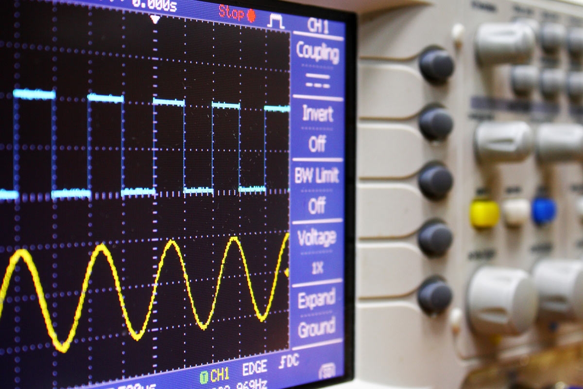
The critical factor for analog signal integrity is the “shape” of the signal as viewed on an oscilloscope. For digital signals, however, the key factor is bit error rate. The transmission bit error rate is the number of failed bits relative to the total number of transmitted bits. A bit error occurs when the receiver cannot properly distinguish between low and high voltage levels. Bit errors in video are visible until the point of image failure. The typical warning signs of bit errors are sparkles in the image, missing lines, or streaking, and these may ultimately lead to a complete loss of image. In video transmission and processing applications, these are often referred to as “artifacts” that negatively impact the visual quality of the transmitted signal.
Some of the factors that affect the bit error rate include:
- Rise Time/Fall Time – the amount of time it takes for a signal to transition from low to high (rise time — the leading edge of the signal), and from high to low (fall time — the trailing edge).
- Signal Swing – the voltage difference between the low state and the high state.
- Clock Period – the amount of time between transitions.
Expanded Leading and Trailing Edges
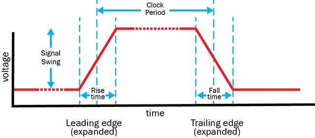
Even though the signals used to represent digital information are depicted as waveforms that have only two discrete states, the transition between voltage levels representing “on” and “off” is not instantaneous. A specific amount of time is required for each transition. These finite time periods are referred to as the rise time and the fall time respectively.
Identifying Leading and Trailing Edges
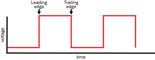
The figure above illustrates an expanded view of the rise and fall time of a digital signal. Rise time/fall time, signal swing, and the clock period are all affected by cable length. Cables that are too long can interfere with proper timing, which can destroy signal integrity.
Signal processing (such as cable equalization) on the receiver’s input can help restore the digital signal and minimize bit errors. Cable equalization is a common and effective way to restore the voltage level and rise/fall time of a digital signal.
Some basic guidelines for minimizing bit errors and maximizing signal integrity include:
- Use only high-quality cables and connectors.
- Minimize cable lengths.
- Avoid extending cables with adapters or “gender changers.”
- Use cable equalization and/or re-clocking circuitry when possible.
RGB Spectrum’s video processing and switching systems are designed to protect signal integrity, with built-in cable equalization that preserves signal clarity over longer distances. We also offer a full range of fiber, HDBaseT and IP extenders that can accommodate resolutions up to 4K.
RGB Spectrum is a leading designer and manufacturer of mission-critical, real-time audio-visual solutions for a civilian, government, and military client base. The company offers integrated hardware, software, and control systems to satisfy the most demanding requirements. Since 1987, RGB Spectrum has been dedicated to helping its customers achieve Better Decisions. Faster.™